← Research · All current investigations
Current evidence context
N0751 · Differential swelling sensor
Evidence context · reviewed 2026-11-01
Current assessment: A well-specified instrument hypothesis with a strong matched-time control; predicted performance remains unmeasured.
Evidence scope: Analytical two-path, first-order response plus simulations with assumed diffusion and readout noise. No device measurements.
Reproduction status: Source-reported computations and derivations; not independently reproduced during publication or this editorial review.
Next milestone: Measure each pathway’s gain, response time and noise; freeze parameters before unseen-waveform and matched-time-control comparisons.
Editorial assessment of retained reports, not a new experiment, full reproduction, peer review or novelty certification. All original hypotheses, negative results and revisions remain archived.
Original supplied report · prose preserved
03 · Differential swelling sensor (N0751) — from idea to a specified instrument
03 · Differential swelling sensor (N0751) — from idea to a specified instrument
Priority 3 · status: mechanism confirmed on paper, turned into a design with a detection floor and a decisive bench test.
The catalogue entry: “A mechanical differentiator could detect rapid chemical changes through the mismatch of two swelling pathways.” The focused dossier already names the right test (concentration steps, ramps and sinusoids; static residual and finite-frequency sensitivity reported separately) and the right kill conditions (gains that do not match leave a false differential; matched time constants make the signal vanish).
What was missing is the transfer function and its consequences. This dossier supplies them, then converts them into a device specification, a detection floor, a bill of materials and a decisive experiment.
1. The mechanism, exactly
Two swelling paths see the same stimulus c(t). Model
each as a first-order Fickian response with gain g_i and
time constant τ_i:
Y_i(s) = g_i / (1 + τ_i s) · C(s)A lever matches the equilibrium gains (ratio
r = g_1/g_2), after which
D(s) = g · [ 1/(1+τ₁s) − 1/(1+τ₂s) ] · C(s)
     = g · (τ₂ − τ₁) · s / [(1+τ₁s)(1+τ₂s)] · C(s)
Three consequences follow immediately, and they are the whole physics of the idea:
At low frequency the output is proportional to the rate of change, not to the level. A step produces a transient that decays to zero (
figures/step_ramp.png, left); a ramp produces a steady output proportional to its slope (right). That is the claimed behaviour, and it is exact in this model.The response is band-pass, not a differentiator without limit. Above
1/τ₁the output falls as1/s. Peak sensitivity is atω* = 1/√(τ₁τ₂)which for a factor-9 pair sits near the geometric mean of the two corner frequencies (
figures/bode.png).If τ₁ = τ₂ the output is identically zero. This is the cleanest control in the experiment, and it is free: the same chemistry cast at the same thickness in both arms must show nothing.
2. Choosing the layers
For a thin hydrogel slab the first-mode time constant is
τ = L²/(π²D) with D the cooperative diffusion
coefficient. Equilibrium swelling displacement scales with thickness, so
thickness sets both gain and speed, and a lever can undo the gain but
not the speed. Taking D = 10⁻¹² m²/s (a stated assumption,
an order of magnitude typical of hydrogel films):
| L₁ / L₂ (µm) | τ₁ (s) | τ₂ (s) | peak frequency | ramp sensitivity (s) | bandwidth |
|---|---|---|---|---|---|
| 10 / 30 | 10.1 | 91.2 | 5.2 mHz | 81 s | 16 mHz |
| 20 / 60 | 40.5 | 365 | 1.3 mHz | 324 s | 3.9 mHz |
| 40 / 120 | 162 | 1459 | 0.33 mHz | 1297 s | 0.98 mHz |
| 10 / 90 | 10.1 | 821 | 1.7 mHz | 811 s | 16 mHz |
The design trade is explicit: thin layers buy bandwidth,
thick ones buy rate sensitivity, and (τ₂ − τ₁) is
literally the number of seconds of stimulus that the differential
integrates — a ramp of 1 unit/s produces τ₂ − τ₁ units of
differential displacement in steady state.
3. The honest limitation: “rapid” means minutes
With D = 10⁻¹² m²/s and a 20 µm film, the half-time is
28 s and the usable band is
millihertz. This construction cannot detect a fast
transient — the diffusion that makes it swell is the same diffusion that
limits it. What it does buy is a genuine rate channel in a
narrow, predictable band, and immunity to slow level drift within that
band.
The claim should therefore be stated as: a differential swelling
head converts a level-sensing hydrogel into a rate-sensing element with
a band set by the two diffusion times, usable from roughly
1/(2πτ₂) to 1/(2πτ₁). Anyone expecting a
fast chemical alarm will be disappointed; anyone measuring the rate of a
slow process (minutes) gets a device with no electronics beyond a
readout.
4. Detection floor and the two failure modes
Monte Carlo (600 trials per rate; readout noise 0.05 µm RMS at 1 Hz, static gain mismatch 0.5 %, mismatch drift 0.2 %/h):
| stimulus rate (units/s) | total change | P(detect) |
|---|---|---|
| 1 × 10⁻⁵ | 0.006 | 0.00 |
| 3 × 10⁻⁵ | 0.018 | 0.04 |
| 1 × 10⁻⁴ | 0.060 | 0.94 |
| 3 × 10⁻⁴ | 0.180 | 1.00 |
| 1 × 10⁻³ | 0.600 | 1.00 |
(figures/detection.png.) Two competing limits appear in
this table and they are the ones to engineer against:
- Noise sets the floor at roughly
3σ/((τ₂−τ₁)√N)≈3 × 10⁻⁵ /s— averaging time, not cleverness, moves it. - Gain mismatch turns the device back into a level
sensor. A residual mismatch
εproduces an outputε·c, so the crossover between “rate” and “level” behaviour is at a total stimulus change ofc* = rate·(τ₂−τ₁)/ε. Atε = 0.5 %andτ₂−τ₁ = 324 s, a 1e-3 /s ramp is 65× above its own leakage — comfortable; a 1e-5 /s ramp is not. The design requirement computed here is gain matching to about 6.5 % for a 10 % leakage floor at the intended operating point; a matched pair is the hard part of the build, and the lever is the tool that makes it adjustable.
5. The decisive experiment (this is the deliverable that matters)
One humidity chamber, one differential head, one reference
hygrometer. Budget under €3,000 (BILL-OF-MATERIALS.md).
- Characterise each path alone. Steps of 5, 10, 20 %
RH at controlled temperature; fit
g_iandτ_i; report the fit residuals. This is the only fitting step. - Freeze the parameters. Predict, without refitting, the differential response to (a) a 0.1 %/s ramp, (b) a 5 mHz sinusoid, (c) a 1 mHz sinusoid, (d) a step.
- Test the matched-time control. Two nominally identical 20 µm arms. Prediction: no output above the noise floor at any frequency. If the control shows a signal, the effect is an artefact of the rig (thermal gradient, chamber asymmetry), not the mechanism.
- Report the residual, not a p-value. The claim is that a first-order pair model predicts the differential output on unseen waveforms. A model that needs refitting per waveform has failed.
Kill criteria, stated in advance: the differential does not follow the predicted phase across the band; or the matched-time control produces a comparable signal; or the residual on the ramp exceeds the predicted ramp signal at the intended operating rate.
6. What this changes in the catalogue entry
- The prediction should be restated as a transfer function, not as “detects rapid changes”.
- “Rapid” must be replaced by a number: the usable band is set by the layer thicknesses, and for realistic films it is millihertz.
- The primary outcome should be the prediction residual on frozen-parameter waveforms, with the matched-time pair as the control — not a correlation with concentration.
- The entry’s own caveats (gain matching, matched time constants, bandwidth) are correct and are now quantified.
7. Limits
- First-order lumped model; real hydrogel films are poroelastic and show a distribution of time constants (stretched exponentials), which will widen and flatten the differential response.
- The stimulus is treated as uniform and instantaneously delivered; chamber transport adds a first order lag that must be measured, not assumed.
D = 10⁻¹² m²/sis an assumption; the design table scales as1/Dand must be recomputed for the chosen chemistry.- No device has been built. Nothing here is a measurement.
Numbers: results/n0751_model.json.
Figures
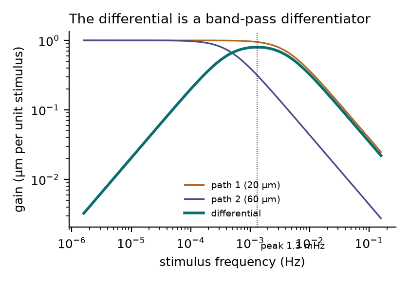
Transfer functions. The differential (teal) is a band-pass differentiator: slope +1 below the first corner, −1 above the second, peak at 1/√(τ₁τ₂) = 1.3 mHz.
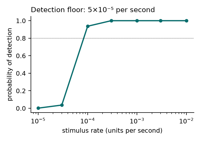
Monte Carlo detection probability against stimulus rate, with 0.5 % gain mismatch, 0.2 %/h drift and 0.05 µm readout noise. Floor near 5×10⁻⁵ per second.
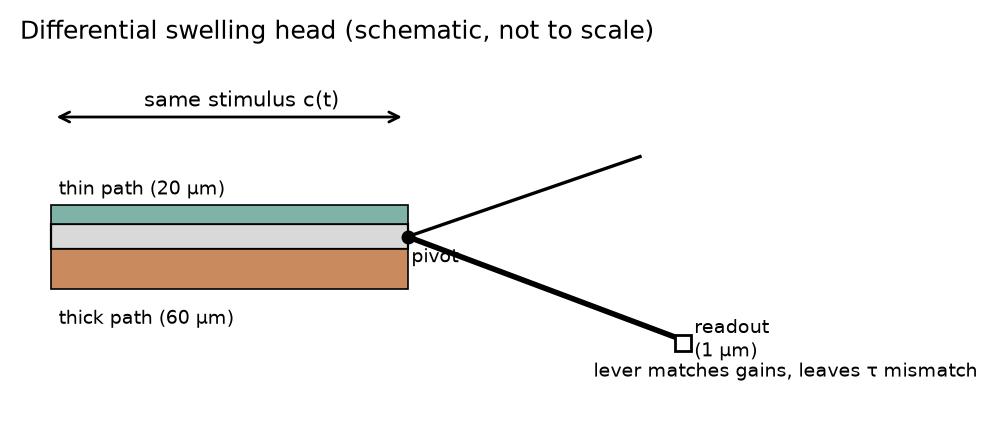
The head: two hydrogel layers of different thickness on a common substrate, a lever that matches equilibrium gains, and a displacement readout. Not to scale.
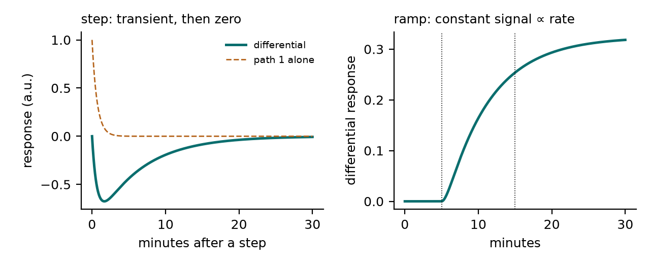
Step response (left): a transient that returns to zero. Ramp response (right): a steady output proportional to the ramp rate.